LG Therma V R290 Combi Unit Installation Guide

HVACBlog28/09/2026

Key Takeaways

• Major components are already built in. The 200-litre domestic hot water tank, backup heater, 3-way valve, and expansion tank are integrated into a single floor-standing cabinet, reducing the number of separate components to install on site. In addition, the system includes a buffer tank, main pump, mixing pump, and mixing valve.*
• No refrigerant work is required. The Combi Unit connects to the R290 Monobloc outdoor unit with water piping only, so no on-site refrigerant piping or handling is needed.
• A compact floor-standing design simplifies installation. With a 600 × 600 mm footprint and rear pipe connections, the unit can fit into kitchen and utility spaces.
• Installation follows a clear sequence from piping to commissioning. Clearly mapped water connections, dedicated cable entries, configurable DIP switches, and a guided Commissioning Wizard help installers work through the installation, configuration, and start-up process.

* Additional components, including the buffer tank, main pump, mixing pump, and mixing valve, are included in 2-Zone models only.

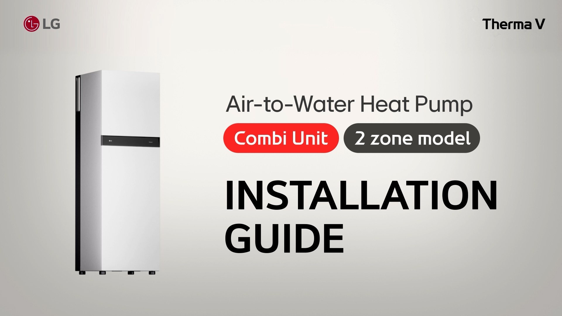
An image showing LG's Therma V R290 Monobloc Combi Unit which stands against the wall.

1. Introduction

For homes that need both space heating and domestic hot water, LG's Therma V R290 Monobloc Combi Unit brings the key components together in one floor-standing cabinet. With a built-in 200-litre Duplex stainless hot water tank, it provides space heating, cooling, and domestic hot water without the need for a separate tank.

The unit connects to an R290 Monobloc outdoor unit through water piping only, so no on-site refrigerant work is required. Its 600 × 600 mm footprint and rear pipe connections also make it practical for kitchen and utility spaces, while providing the access needed for installation and servicing.

This guide takes you through the installation process from positioning and water piping to electrical wiring, system configuration, and commissioning.

* This guide is a visual overview to accompany LG's installation video. It doesn't replace the full installation manual, and installation must be carried out by a qualified professional in line with local regulations.
* This guide covers the 2 zone model of the LG Therma V R290 Monobloc Combi Unit. Installation steps may differ for the 1 zone model.

2. Site Preparation

With the right unit identified, the first job on site is preparing where it will go. Before moving the unit into position, confirm the floor is solid and level, drainage is accessible, and the required service clearances are met. The Combi Unit is a floor-standing cabinet weighing roughly 131 kg, so the base and its surroundings matter for safety, drainage, and future maintenance access.

2-1. Prepare location:
• Solid, level floor able to bear the filled unit's weight — remember the 200 L tank adds significant load once charged.
• Waterproof floor surface with access to household drainage.
• No flammable materials nearby.
• Nothing in front of the unit that would block access.

2-2. Confirm minimum clearance:
• Rear:
100 mm
• Right side: 500 mm
• Top: 300 mm
• Front: 600 mm

A rendering image shows a precise dimension of LG Therma V Combi Unit.

<This image shows the overall dimensions of the mounted LG Therma V Combi Unit.>

One space-saving point worth noting here: because the pipe connections run from the rear, the unit can fit into kitchen and utility spaces, while its 600 × 600 mm footprint fits most layouts.

3. Positioning and Panel Access

Now that the space is ready, it's time to move the unit in and open it up for the connections ahead. Because the Combi Unit is floor-standing rather than wall-mounted, it tilts into position rather than hanging on a bracket — and given its weight, this is a two-person job.

3-1 Move the unit into place:
• Work with two people, holding the bottom and rear handles.
• Tilt the unit backward to guide it safely into its final position.

3-2. Opening Up the Unit for Installation:
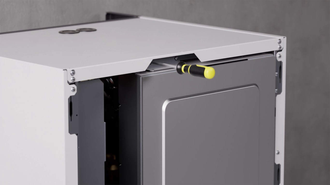
• Loosen the bottom screws to lower the control panel (HMI).
• Release the screws at the top of the indoor unit and detach the front panel.
• Unscrew the fixings connecting the control box to the side panel, then open the control box.

<This video shows how to unscrew and remove the front and inner service panels of the LG THERMA V Combi Unit for internal component access>

Worth remembering for later: the control box is hinged, so once the front panel is off it swings open in a single step for wiring and servicing — no full disassembly needed.

4. Water Piping

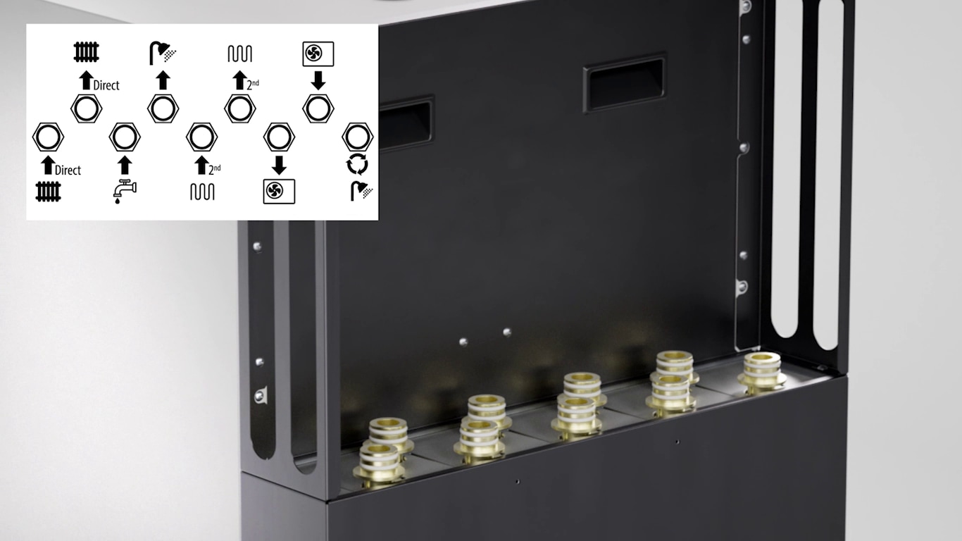
With the unit in place and open, the next stage is the plumbing — connecting the water circuits that carry heat around the system. The Combi Unit uses clip-type, plain-end connectors, so pipes press-fit into place rather than being threaded. That makes them quicker to fit and easy to take apart later for servicing. Work through the ports using the port map on the unit as your guide.

4-1. Connect the circuits:
• Direct circuit
— the primary heating/cooling circuit (e.g. radiators).
• Mixing circuit (2nd circuit) — the second circuit, typically underfloor heating at a lower temperature.
• Domestic hot water — connect the hot water outlet and the city (mains) water supply.
• Re-circulation — optional; if you're not using a re-circulation pipe, close the hole in the straight pipe.
• Outdoor unit — connect the flow and return pipes to the R290 Monobloc outdoor unit.

<This video shows how to set Option Switch 1 and Option Switch 2 on the PCB to configure Modbus,
communication modes, antifreeze protection, and cycle types on the LG THERMA V Combi Unit.>

4-2. Sealing and Securing Each Joint:
• Use a press-fitting tool to tighten each connection firmly.
• To adapt the default pipework to the site, remove the 9 clips to detach it and refit as needed.
• Fit a strainer on the outdoor-unit connection to protect the system.

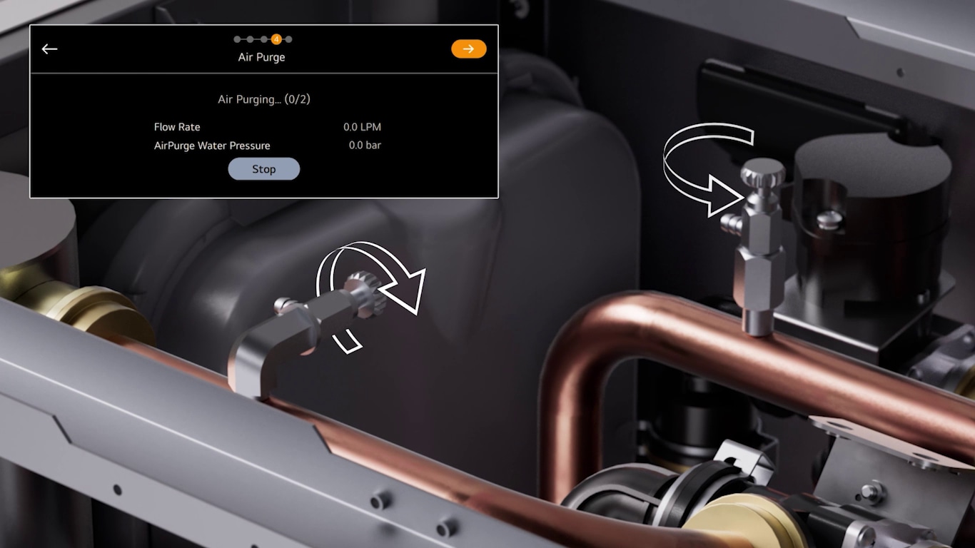
4-3. Charging the System with water and purge the air:
• Open the air vent caps on both the indoor and outdoor units.
• Open all valves in the water circuit and connect the water supply.
• Once the air is fully purged, close all air vents tightly.
• Insulate all connections to prevent condensation and dew.
• Lastly, close the water supply valve or remove the hose.

* The heating circuit must never be permanently connected to the mains water supply as an open-loop system. Use a system de-coupler or another approved filling method to keep the circuits separated, in line with local regulations.

<This video shows how to manually open the air purge valves and run the automatic air purging process on the LG THERMA V Combi Unit.>

5. Electrical Wiring

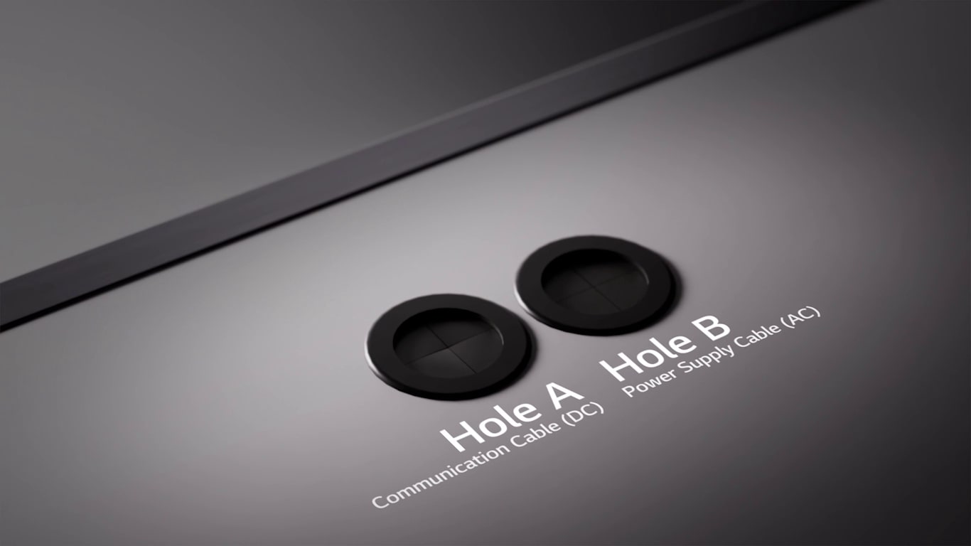
With the water side complete, we move to the electrical connections. The Combi Unit has two separate cable entries: Hole A for low-voltage and sensor cables, Hole B for power. Before you touch any wiring, switch off the power supply.

* All electrical work, including wiring of the indoor unit, backup heater, and protection devices, must be carried out by a licensed electrician in accordance with national wiring standards and LG’s official installation manual.

5-1. Routing Each Cable Through the Correct Entry:
• Hole A
— communication (DC) and sensor cables.
• Hole B — power supply cables (indoor unit and backup heater).
• Use round pressure (ring) terminals at the power terminal block, and don't over-tighten the wiring — the control box still needs to open after the connections are made.

<This video shows how to route DC communication cables through Hole A and AC
power supply lines through Hole B on the top of the LG THERMA V Combi Unit.>

5-2. Working Through the Terminal Blocks in Order:
• Communication
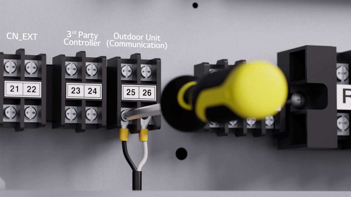
— connect the outdoor unit communication cables to terminals 25 and 26.
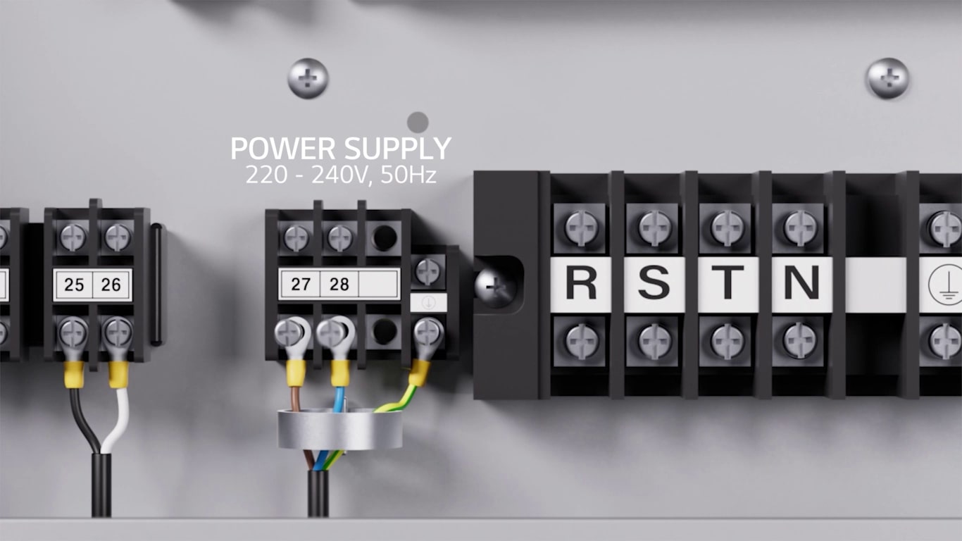
• Main power — route the power cable through Hole B and connect to terminals 27 and 28 (220–240 V, 50 Hz), including earth.
• Backup heater — connect the backup heater power cable to its own terminal block, including earth.

<This video shows how to wire and fasten the outdoor unit communication cables to terminals 25 and 26 on the LG THERMA V Combi Unit terminal block.>

<This video shows how to connect the 220–240V AC main power supply to terminals 27 and 28
and wire the backup heater terminal block on the LG THERMA V Combi Unit.>

5-3. Matching the Backup Heater Wiring to Your Power Supply:
• 1-phase, 1-step (3 kW):
connect L1 and N.
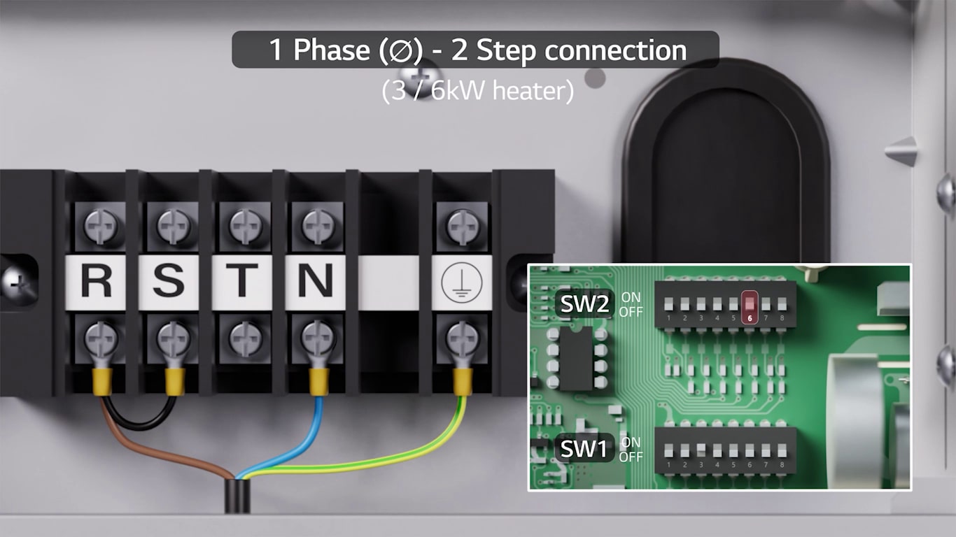
• 1-phase, 2-step (3/6 kW): connect L1, L2, and N, using the L1–L2 harness supplied in the bag with the manual.
• 3-phase, 3-step (3/6/9 kW): connect R, S, T, and N.

For reference, the remaining terminals are 21–22 (CN_EXT) and 23–24 (3rd-party controller).

* For exact wiring diagrams, cable sizing, and protection devices, always refer to the official LG installation manual and local electrical codes.  

<This video shows how to configure the PCB DIP switches (SW1 and SW2) for
1-phase and 3-phase backup heater capacity steps on the LG THERMA V Combi Unit.>

6. System Configuration

With the wiring done, the next step is telling the system what you've actually installed — this is handled by the DIP switches on the indoor PCB. Make sure the power supply is switched off before you touch them. The factory defaults suit a standard setup, so you only need to change the switches your particular installation calls for.

6-1. The Main Settings to Check:
• SW2-2
- accessory information: set these to match your setup, whether that's the heat pump with a DHW tank with an outdoor unit, or reserved.
• SW2-4 — cycle: leave OFF for heating only, or set ON to enable cooling.
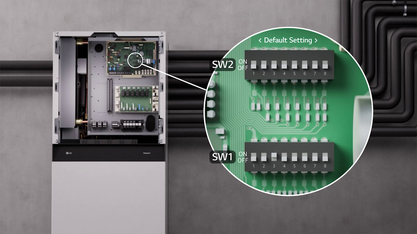
• SW2-6 and SW2-7- backup heater capacity: set this combination to suit the heater fitted, matching the phase and step wired in Section 5.
• SW1-3 — outdoor-to-indoor communication: ON for the RS-485 method (9600 bps), OFF for the AC method.
• SW1-8 — antifreeze agent: ON if antifreeze is used (the CN_ANTI_SW bridge must be disconnected to enable).

<This video shows how to set Option Switch 1 and Option Switch 2 on the PCB to configure Modbus,
communication modes, antifreeze protection, and cycle types on the LG THERMA V Combi Unit.>

The PCB label carries the full DIP switch reference table — check it, and set only the switches relevant to your components and site conditions.

6-2. Bringing the Unit to Life and Setting It Up Through the HMI
• Reattach the front panel by sliding it down into place.
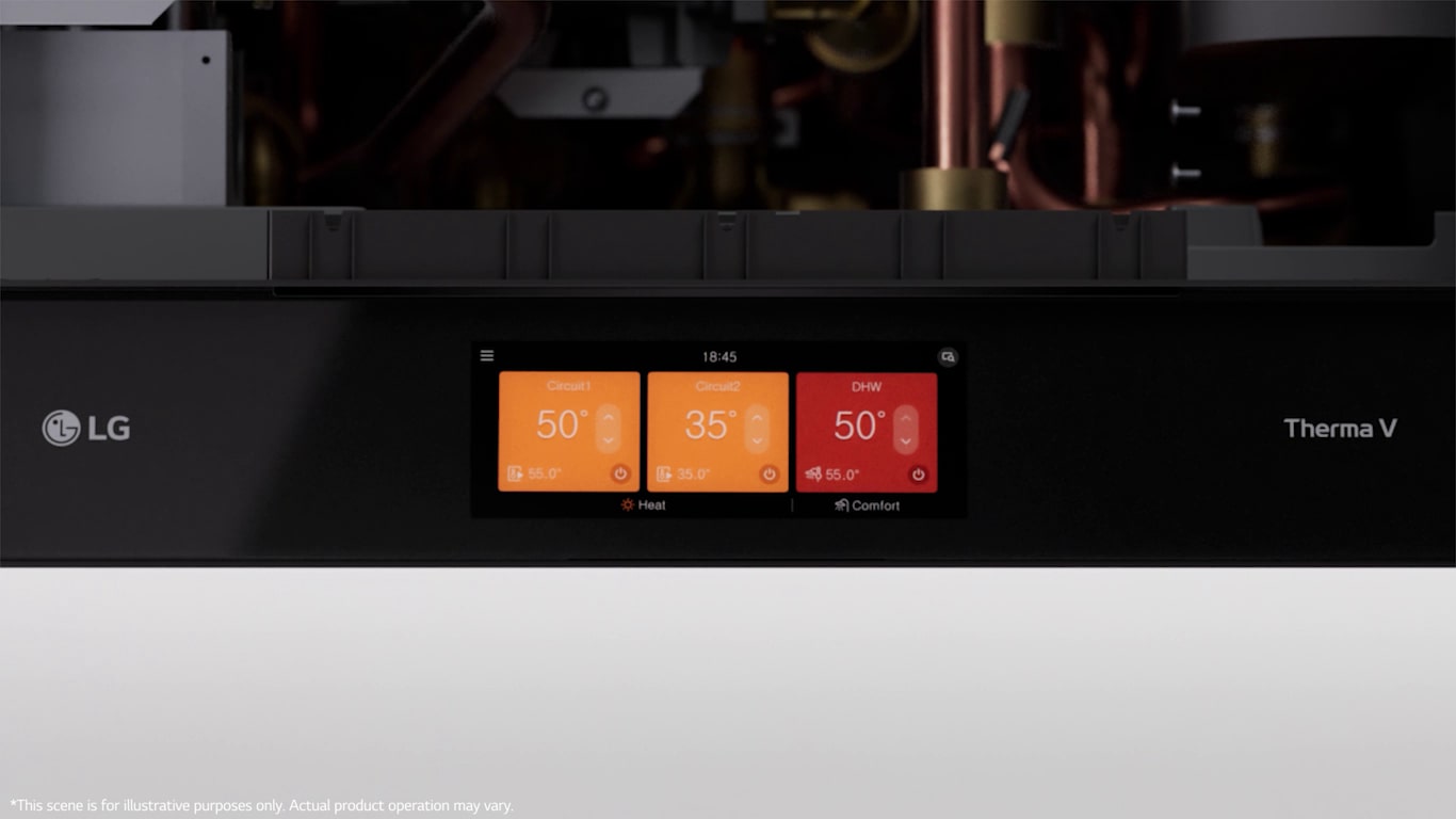
• Power on the unit — the HMI (6.8-inch touch screen) starts up.
• Set the control mode, circuits, pump operation, and target temperatures for heating, cooling, and DHW.

* Never set the antifreeze switch (SW1-8) to ON unless antifreeze agent has actually been added to the system. Enabling the setting without glycol in the circuit can allow the water to reach temperatures it isn't protected against.

7. Commissioning

With everything installed and configured, the final stage is commissioning — the checks and tests that confirm the system is safe to run before you hand it over. Taking the time here catches installation faults early, and the Combi Unit's guided setup wizard makes the process straightforward.

7-1. Begin with the Pre-Start Checks:
• Confirm the charged water pressure reads between 2.0 and 2.5 bar, and never above 3.0 bar.
• Check that all air has been purged and the air vents are closed.
• Confirm the communication and power wiring are correct and properly separated.
• Verify all valves in the water circuit are open.

7-2. Running the Tests and Starting Up:
• Run the Backup Heater Wiring Test from the HMI setup menu to confirm the heater is wired correctly.
• Use the Commissioning Wizard to complete the installer settings and start-up in guided steps.
• Run the pump test from the service menu.
• Power the unit on ahead of first use to pre-heat the compressor before full operation.

<This video illustrates the guided commissioning sequence on the LG Therma V Combi Unit.>

7-3. Bringing the System Online:
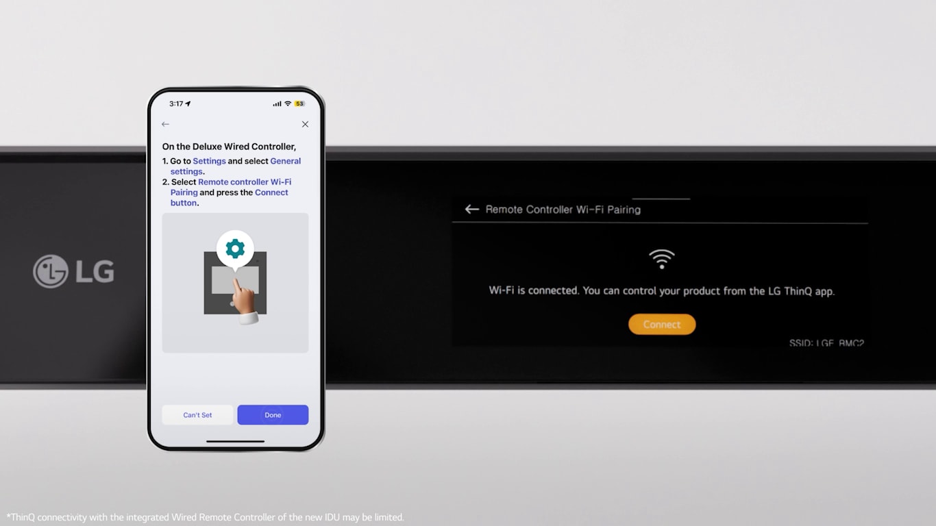
• In the LG ThinQ app, tap Add devices and select Deluxe Wired Controller.
• On the HMI, go to Settings → General Settings → Remote Controller Wi-Fi Pairing and tap Connect.
• Once paired, the system is ready for remote monitoring and control.

<This video shows how to pair the LG THERMA V Combi Unit wired controller
with the LG ThinQ mobile app via Wi-Fi for smart remote monitoring and control.>

And that's it — the installation is complete, and the Therma V R290 Combi Unit is ready to operate.

Watch Full Video

LG HVAC solutions video featuring the installation guide of LG Therma V Combi Unit with visual imagery and explanation.

FAQs

Q.

Is the LG Therma V R290 Combi Unit suitable for kitchens and utility spaces? 

A.

Yes. Its compact 600 × 600 mm footprint makes the unit suitable for installation in most kitchen and utility spaces, while the rear pipe connections help make efficient use of available space.

Q.

What's the difference between the 1 zone and 2 zone Combi Unit model?

A.

The 1 zone model runs a single heating/cooling circuit plus domestic hot water. The 2 zone  model adds a built-in 16-litre buffer tank, a direct pump group, and a mixing pump group, so two circuits — for example radiators and underfloor heating — can operate at different temperatures.

Q.

Does the Combi Unit need refrigerant piping on site?

A.

No. It connects to the R290 Monobloc outdoor unit with water piping only, so no on-site refrigerant work is required.

Q.

How large is the hot water tank?

A.

The Combi Unit has a built-in 200-litre domestic hot water tank made of Duplex stainless-steel.

Q.

Does it require a separate Wi-Fi modem?

A.

No. Wi-Fi  modem is built into the HMI controller. Pairing is done through the LG ThinQ app with no additional hardware.

Q.

Who should install the Combi Unit?

A.

 Installation must be carried out by a qualified professional in line with local regulations. This guide is a visual overview and does not replace the official installation manual.

More about LG HVAC

* Products and solutions may vary according to country and operating conditions.

red image

red image

Get Your Expert Consultation

Connect with our specialists for tailored solutions — every question matters to us.

white bg color image on colorful image

white bg color image on colorful image

Subscribe to LG HVAC Blog
Newsletter